

How To Arduino Uno With 1 Meter 5050 Led Light Strip Using Shift Register
The ascent of LED lighting has been stratospheric, and it's easy to see why. They are inexpensive to produce, swallow significantly less power than other lighting options, and in most cases don't get hot, making them safety for a diverseness of uses.
I of the most mutual LED products is the LED strip. In this article, nosotros will comprehend how to set upwards the 2 most common types with an Arduino. These projects are very simple, and even if you are a beginner with Arduino or DIY electronics, y'all volition be able to exercise this.
We volition also use the Arduino IDE to control them. This projection uses an Arduino Uno, though you lot could utilise almost any compatible board (such as the NodeMCU).
Choose Your Strip
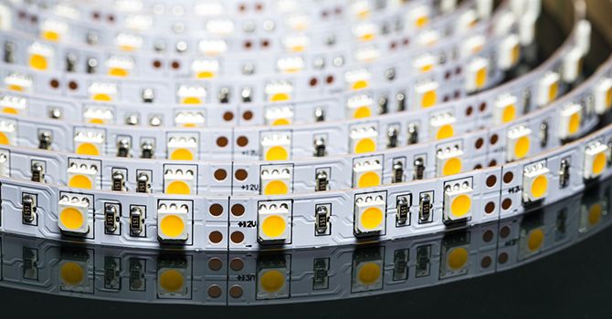
When shopping for LED strips there are a few things to consider. Kickoff is functionality. If you are planning to utilise the strips mostly for ambient lighting, and so a simple 12v RGB LED strip (SMD5050) would be the correct choice.
Many of these strips come with an infrared remote to control them, though in this project we will be using an Arduino to instead. Spend a little time shopping around, at the fourth dimension of writing it was possible to become these strips for as footling as $one per meter.
If you lot want something a little college tech, consider the WS2811/12/12B. These strips (sometimes referred to every bit Neopixels) have integrated chipsets which allow them to be addressed individually. This means they are capable of more just ambient lighting.
You can utilize them to build a cheap LED pixel display from scratch. You can even use them to make your own personal indoor storm cloud lamp.
These strips only require 5v to ability them. While information technology is possible to power modest amounts of them directly from an Arduino board, it is generally a good idea to utilise a separate 5V power supply to save yourself from the smell of fried Arduino. If you are looking for individually programmable LEDs, these are for you. At the time of writing, they are bachelor for around $4 per meter.
Another thing to consider is where these strips are probable to be used. Both of these types of strip come in varying lengths, LED densities (the number of LEDs per meter), and differing degrees of weatherproofing.
When looking at LED strips, pay attending to the numbers on the list. Usually, the offset number will be the number of LEDs per meter, and the letters IP followed by numbers will be its weatherproofing. For example, if the listing says 30 IP67, this means there will exist 30 LEDs per meter. The half-dozen denotes it is completely sealed from dust, and the 7 ways it is protected against temporary submersion in water. (Learn more than nearly weatherproofing and IP ratings.) In one case you lot have your called LED strip, information technology's time to link it up with an Arduino. Let'southward kickoff with the SMD5050.
Getting Connected
In order to connect up a 12v LED strip to an Arduino, y'all will need a few components:
- 12v RGB LED strip (SMD5050)
- 1 x Arduino Uno (whatsoever uniform board will practise)
- three x 10k Ohm Resistors
- 3 x Logic Level N-channel MOSFETs
- 1 x Breadboard
- Hookup wires
- 12v Ability Supply
Before setting up the circuit, permit's talk about MOSFETs.
Whenever you lot are decision-making something which is higher voltage than your microcontroller, you need something in between to cease your board getting fried. Ane of the simpler ways to practise this is to use a MOSFET. Past sending pulse width modulation (PWM) signals to the gate leg, information technology's possible to control how much power passes between the drain and source legs. Past passing each of the LED strip'southward colors through the MOSFET, you lot can command the brightness of each individual colour on the LED strip.
When using microcontrollers, information technology is important to use logic level components in order to ensure things work the way you want them to. Make sure your MOSFETs are logic level and not standard.
Set up up your circuit like this:
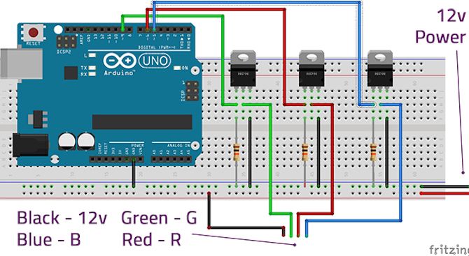
- Connect Arduino pins 9, 6, and five to the gate legs of the three MOSFETs, and connect a 10k resistor in line with each to the basis track.
- Connect the Source legs to the ground runway.
- Connect the Bleed legs to the Green, Crimson, and Blue connectors on the LED strip.
- Connect the power rail to the +12v connector of the LED strip (note that in this epitome the power wire is blackness to match the colors of the connectors on my LED strip).
- Connect the Arduino ground to the basis rail.
- Connect your 12v power supply to the ability rails.
Almost LED strips have Dupont [Broken URL Removed] connectors, which are piece of cake to connect to. If yours don't yous may need to solder wires to the LED strip. Don't panic if you are fairly new to soldering, it'south an like shooting fish in a barrel job, and we have a guide to getting started with soldering should you need information technology.
We volition be powering our Arduino board by USB for this project. You could cull to power your board using the VIN pin, but make sure yous know the ability limitations for your board before doing this.
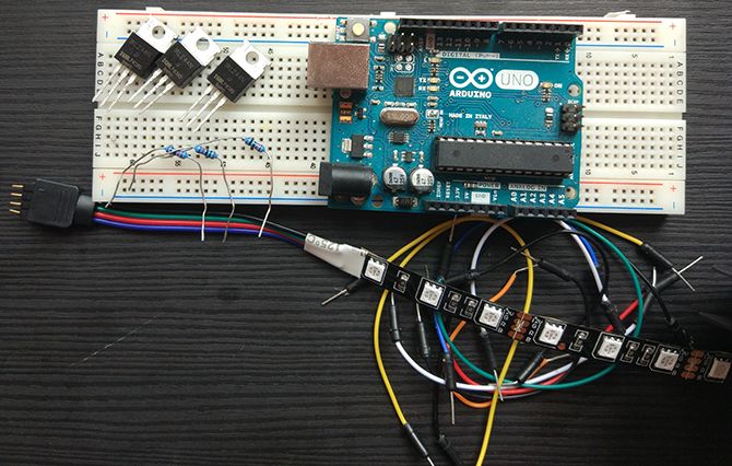
When your circuit is complete it should look something like this:
Now that you have connected everything, it's time to make a unproblematic Arduino sketch to control information technology.
Fade It Upwards
Connect your Arduino lath to your computer via USB and open upward the Arduino IDE. Make sure you have the correct lath and port number selected for your board in the Tools > Board and Tools > Port menus. Open a new sketch and save it with an appropriate proper name.
This sketch will fade the lights in one colour at a fourth dimension, go on them on for a few seconds, then fade them out until they are off once again. Yous can follow through here and brand the sketch yourself, or simply download the complete code from GitHub.
Begin by defining which pins will exist used to control the MOSFETs.
          #define RED_LED 6
#ascertain BLUE_LED 5
#ascertain GREEN_LED 9
Next you lot need some variables. Create an overall effulgence variable, along with a variable for each individual color's brightness. Nosotros will just be using the primary effulgence variable for turning the LEDs off, then fix it to the maximum brightness value of 255 here.
yous will also need to create a variable to control how fast the fading will happen.
          int brightness = 255;
int gBright = 0;
int rBright = 0;
int bBright = 0;
int fadeSpeed = 10;
In your setup office we will set our Arduino pins to output. We will likewise call a couple of functions with a 5 second delay in between. These functions don't be yet, only don't worry, we'll get to them.
          void setup() {
            pinMode(GREEN_LED, OUTPUT);
            pinMode(RED_LED, OUTPUT);
            pinMode(BLUE_LED, OUTPUT);
            TurnOn();
            delay(5000);
            TurnOff();
}
Now create the TurnOn() method:
          void TurnOn() {
            for (int i = 0; i < 256; i++) {
            analogWrite(RED_LED, rBright);
            rBright +=1;
            delay(fadeSpeed);
            }                 for (int i = 0; i < 256; i++) {
              analogWrite(BLUE_LED, bBright);
              bBright += 1;
              delay(fadeSpeed);
              }
              for (int i = 0; i < 256; i++) {
              analogWrite(GREEN_LED, gBright);
              gBright +=one;
              delay(fadeSpeed);
              }
}
These iii for loops take each colour upward to its full brightness over a fourth dimension specified by the fadeSpeed value.
Finally you demand to create the TurnOff() method:
          void TurnOff() {
            for (int i = 0; i < 256; i++) {
            analogWrite(GREEN_LED, brightness);
            analogWrite(RED_LED, effulgence);
            analogWrite(BLUE_LED, brightness);                     brightness -= 1;
              delay(fadeSpeed);
              }
}
void loop() {
}
This method applies our brightness variable to all three color pins and reduces them to zero over a menstruum of time. We need an empty loop method here as well, in order to avoid compilation errors.
Once you lot have completed this sketch, relieve information technology. Verify the sketch and upload it to your Arduino board. If you lot are getting errors, check through the code again for any pesky typos or missing semicolons.
Now you should encounter your LED strip ramp up each color individually, holding the white color for 5 seconds, and and then uniformly fade to naught:
If y'all are having any difficulties, double check your wiring and code again.
This projection is a simple way to become started, but the ideas covered in it can be expanded on to make really constructive lighting. With just a few more than components you lot could create your own sunrise alarm. If you lot got a starter kit with your Arduino you could employ any button or sensor to trigger your LEDs when yous enter the room, for instance:
At present that nosotros have covered the SMD5050s, let's move on to the WS2812B strips.
Bright Ideas
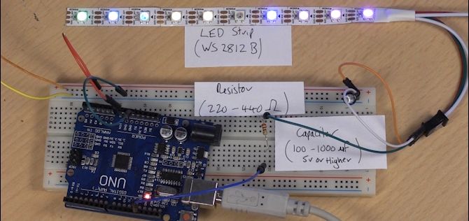
These strips require fewer components to get them running, and in that location is some elbowroom as to exactly what values of components you tin can use. The capacitor in this excursion makes certain that the 5v LEDs go a steady power supply. The resistor ensures the data indicate received from the Arduino is free from any interference.
You will need:
- WS2811/12/12B 5v LED strip (all three models have integrated chips and work much the same way)
- 1 x Arduino Uno (or similar compatible lath)
- ane x 220-440 Ohm Resistor (anything between these two values is fine)
- 1 10 100-1000 microFarad Capacitor (anything between these two values is fine)
- Breadboard and hook up wires
- 5V power supply
Fix your circuit equally shown in the diagram:
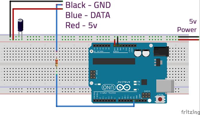
Take notation that the capacitor must exist the correct orientation. You lot can tell which side attaches to the footing rail by looking for the minus (-) sign on the torso of the capacitor.
This time round we are powering the Arduino using the 5v Ability supply. This makes the projection stand solitary once nosotros are done, though there are of import things to notation hither.
Firstly, make sure that your board tin accept 5v power in before attaching it to the ability source. Almost all development boards run at 5v through the USB port, just the power input pins on some can sometimes skip the voltage regulators and turn them into toast.
Also, it is good practice to make sure that multiple separate power sources are not continued to the Arduino -- disconnect the USB cable whenever yous are using an external power supply.
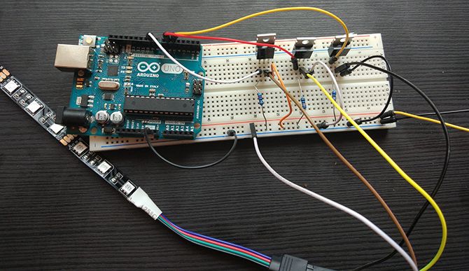
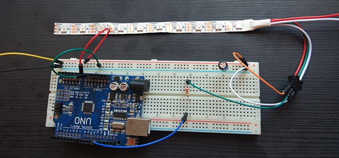
Once yous are plugged in it should look like this:
At present that our LED strip is wired in, let'due south move on to the lawmaking.
Dancing Lights
In order to safely program our board, disconnect the VIN line from the power line. You'll reattach it later.
Attach your Arduino to the reckoner and open the Arduino IDE. Check that y'all take the correct lath and port number selected in the Tools > Board and Tools > Port menus.
We volition be using the FastLED library to test out our setup. Y'all can add the library by clicking on Sketch > Include Library > Manage Libraries and searching for FastLED. Click install, and the library will be added to the IDE.
Under File > Examples > FastLED select the DemoReel100 sketch. This sketch cycles diverse things which can be done with the WS2812 LED strips, and is incredibly piece of cake to gear up up.
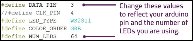
All you lot need to change is the DATA_PIN variable so that it matches pin xiii, and the NUM_LEDS variable to define how many LEDs are in the strip you are using. In this case, I am using just a minor line of 10 LEDS cutting from a longer strip. Use more than for a bigger light bear witness!
That's it! Upload the sketch to your board, disconnect the USB cablevision and plough on your 5v power supply. Finally, reattach the Arduino's VIN to the power line and scout the show!
If cipher happens, check over your wiring and that y'all specified the correct Arduino pin in the demo sketch.
Countless Possibilities
The demo sketch shows off some of the many possible combinations of effects that tin exist achieved with the WS2812 strips. Aslope being a pace upwards from regular LED strips, they tin can exist put to practical utilise too. A good next projection would be edifice your own ambilight for your media center.
While these strips are definitely more than functional than the SMD5050s, don't discount the standard 12v LED strips quite yet. They are unbeatable in terms of cost, and there are a huge number of applications for LED light strips.
Learning to work with LED strips is a good manner to get familiar with basic programming on the Arduino, merely the best way to larn is by tinkering. Modify the above code and see what y'all tin do! If all of this was a bit too much for yous, consider starting with these Arduino projects for beginners.
Image Credits: mkarco/Shutterstock
About The Author


Source: https://www.makeuseof.com/tag/connect-led-light-strips-arduino/
Posted by: smithjould1995.blogspot.com
0 Response to "How To Arduino Uno With 1 Meter 5050 Led Light Strip Using Shift Register"
Post a Comment